Mesh to Micron Converter
- Last formula update:

Decimal & Rounding Policy
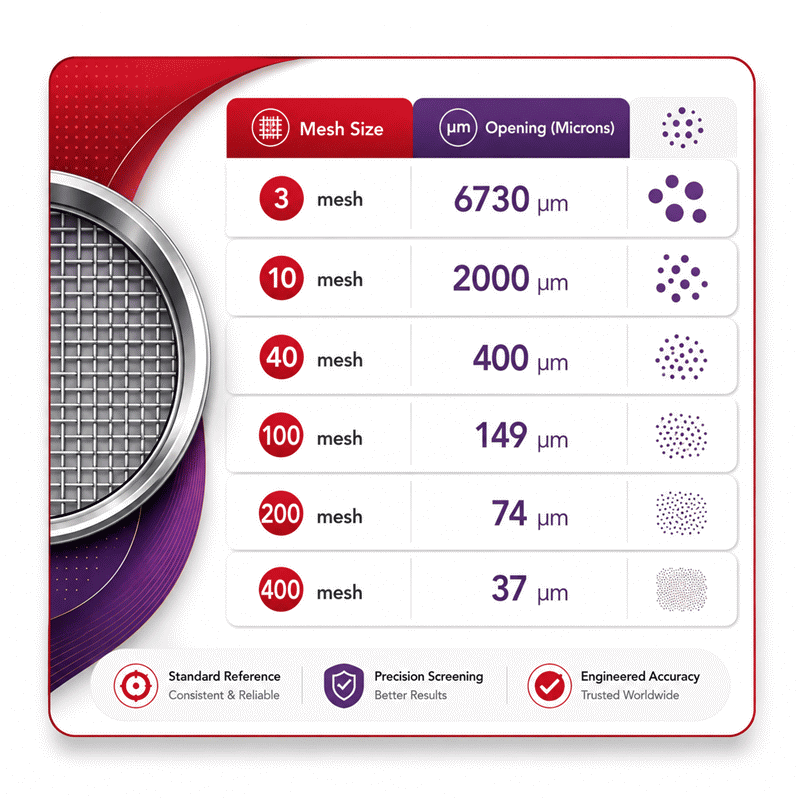
- Reference-table conversions use the listed mesh and micron values directly without adding unnecessary decimal rounding.
- For approximate conversions between 50 and 400 mesh, calculations use micron = 14,900 / mesh or mesh = 14,900 / micron and retain full precision during calculation.
- Calculated results are rounded only for display, with up to 6 decimal places when additional precision is useful.
- Trailing zeros are removed automatically so results remain clean and easy to read.
- Exact reference values take priority over rounded approximations whenever a matching mesh or micron value is available.
- Intermediate values are never rounded, helping prevent cumulative rounding errors in reverse mesh-to-micron conversions.
Valid range
- Mesh size: Supported reference-table values range from 3 to 400 mesh, while approximate calculations are limited to 50 to 400 mesh.
- Micron size: Supported reference-table opening sizes range from 37 to 6,730 µm, with reverse approximation limited to the range corresponding to 50 to 400 mesh.
- Calculation range: Exact listed mesh-to-micron values use the reference chart; non-table values use micron = 14,900 / mesh or mesh = 14,900 / micron only within the supported approximation range.
- Input validity: Mesh and micron values must be positive, finite numbers, and unsupported non-table values outside the valid calculation range are rejected.

Felovyn Quarnwick
Reviewers:
Meravie Quellmont
Herixon Vosswick
Check our editorial policy
September 8, 2026
1.0.0
Initial calculator and formula release.
Our engineers are here to help you get it right.
How Does the Mesh to Micron Converter Give You the Right Result?
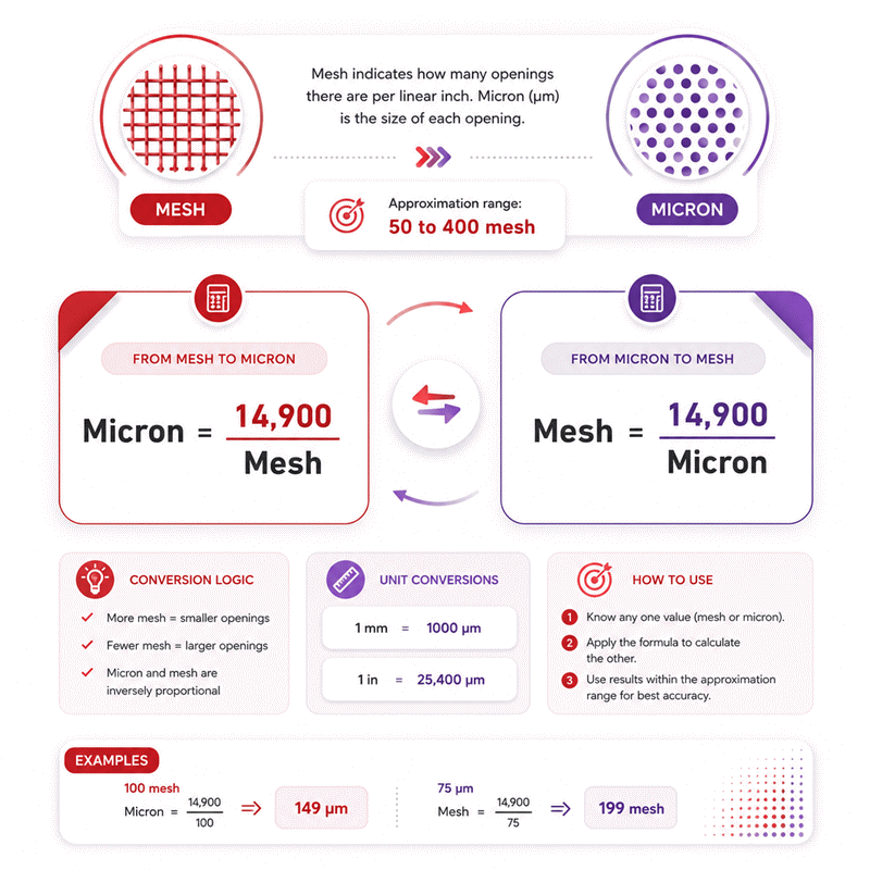
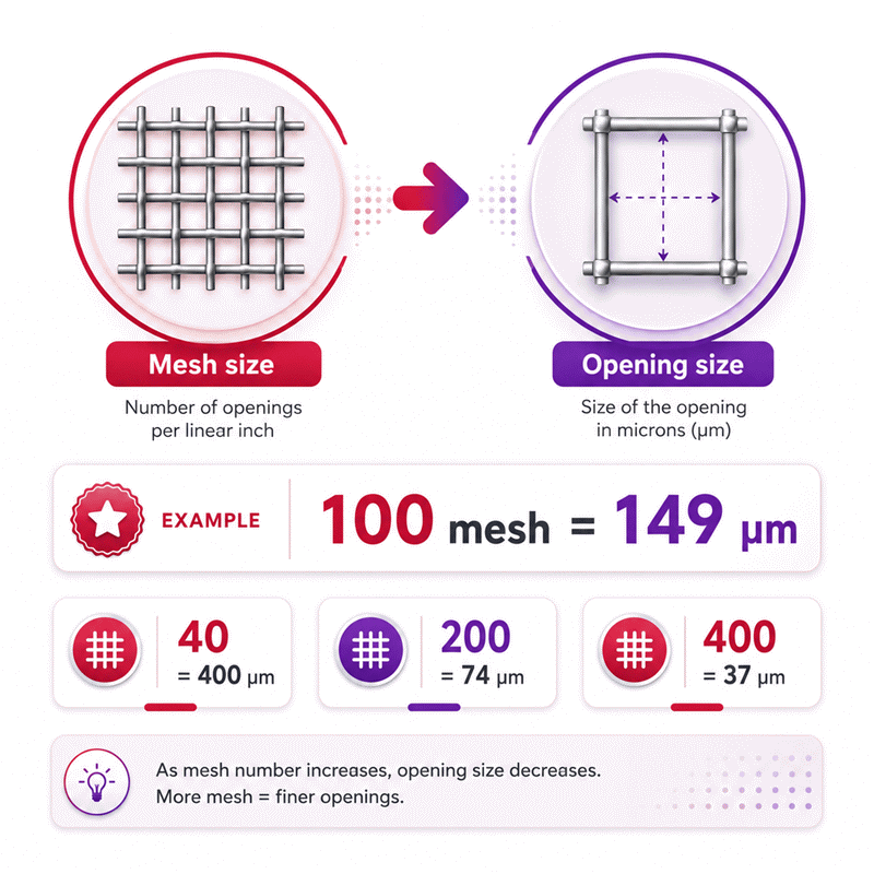
Mesh to Micron Converter calculations connect a screen’s mesh number with its corresponding opening size in micrometers. Mesh count describes the number of openings per linear inch, while micron size describes the physical opening width. Because wire thickness affects the real aperture, mesh and micron values do not have one universal exact conversion formula.
- Exact values available in the reference table are used before any approximation.
- For supported non-table values from 50 to 400 mesh, the calculator uses micron = 14,900 / mesh.
- Reverse solving uses mesh = 14,900 / micron within the supported approximation range.
- Higher mesh numbers generally represent smaller screen openings.
- Wire diameter, weave construction, and screen design can affect actual opening size.
- Reference values are useful for screening, filtration, powder processing, and particle-size comparison.
- Industrial users should confirm critical aperture requirements with the actual screen specification.
The Mesh to Micron Converter supports both forward and reverse solving, helping users move quickly between mesh and opening-size requirements. Reference-table matches provide the preferred conversion path, while supported intermediate values use the defined approximation. This distinction helps users interpret results correctly and avoid treating an estimated value as a certified physical aperture.
Assumptions used in this calculator
- Exact reference-table values take priority over approximate mesh-to-micron calculations.
- Non-table conversions use the defined approximation only within supported ranges.
- Mesh and micron values are assumed to be positive and finite.
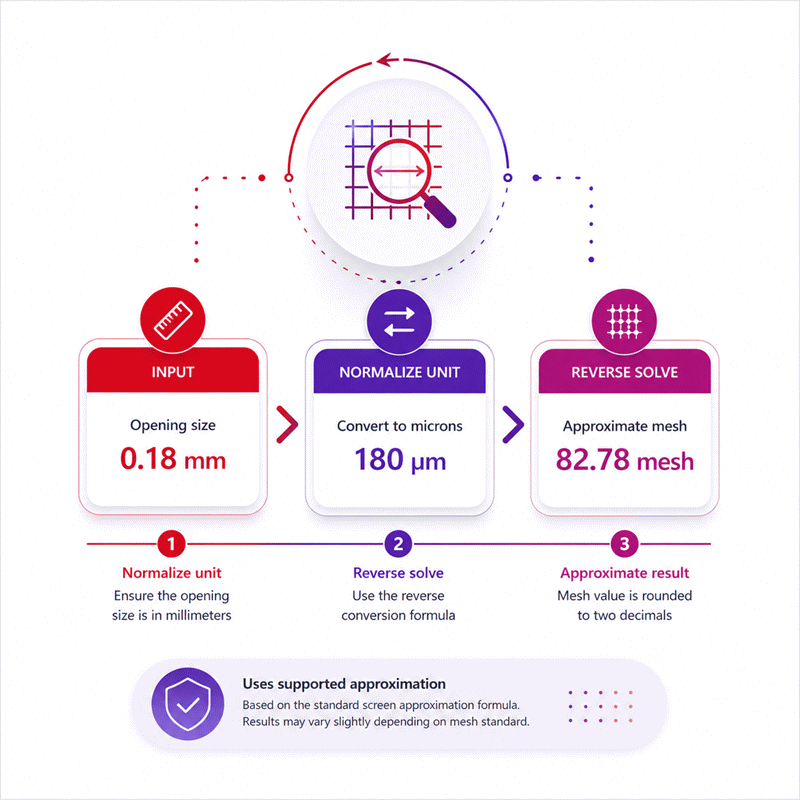
- Opening size is normalized to micrometers before calculations are performed.
- Unit conversions preserve the same physical opening size across supported units.
- Mesh number represents openings per linear inch under standard sieve terminology.
- Actual sieve openings may vary with wire diameter and manufacturing tolerances.
- Calculated values are estimates unless confirmed by an applicable sieve standard.
- Industrial users should verify results against certified equipment specifications when required.
- Laboratory decisions should use calibrated measurements where regulatory accuracy is required.
- Intermediate calculations retain full precision before final display formatting is applied.
- Unsupported values outside the defined calculation range are not extrapolated.
- Results assume correctly entered values, compatible units, and valid measurement conditions.
Results are rounded for display.
Internal calculations use full precision.
Formulas Used in Mesh to Micron Converter :
1. Opening Size Unit Normalization
The entered opening size is first converted to micrometers so every calculation uses one consistent base unit.
2. Exact Reference-Table Rule
When an exact mesh or micron value exists in the reference table, the corresponding stored pair is used directly in either conversion direction without applying the approximation formula.
3. Approximate Mesh-to-Micron Relationship
For a supported non-table value from 50 through 400 mesh, this inverse relationship is used for both forward and reverse calculation. Exact reference-table pairs always take priority.
Variable Definitions
- m = mesh number, representing the number of openings per linear inch.
- μ = opening size expressed in micrometers.
- x = opening-size value entered or displayed in the selected unit.
- ku = unit-to-micrometer conversion factor: 1 for µm, 1,000 for mm, and 25,400 for in.
- T = stored reference table containing the supported exact mesh and micron pairs.
Variables & Definitions
View a complete list of all variables used in this calculator, including definitions and units
Mesh to Micron Converter Variables and Units
| Variable | Meaning | Unit | Calculation Role |
|---|---|---|---|
| m | Mesh number representing the number of openings per linear inch | mesh | Primary mesh value used for exact table lookup or the supported approximate conversion |
| µ | Opening size expressed in the calculator base unit | µm | Normalized particle or sieve opening size used in forward and reverse calculations |
| x | Opening-size value entered or displayed in the selected unit | µm, mm, or in | User-facing opening value converted to or from the micrometer base unit |
| ku | Conversion factor from the selected opening-size unit to micrometers | µm per selected unit | Uses 1 for µm, 1,000 for mm, and 25,400 for in |
| T | Stored set of exact mesh and micron reference pairs | mesh / µm pairs | Provides exact values before any approximate calculation is considered |
Unit Conversion Table
Mesh to Micron Unit Conversion Reference Table
| Unit Group | Unit Name | Symbol | Equivalent in Micrometers | Used For |
|---|---|---|---|---|
| Scientific Units | Micrometer | µm | 1 µm = 1 µm | Base opening-size unit for mesh-to-micron calculations and reference-table values |
| Popular Units | Millimeter | mm | 1 mm = 1,000 µm | Larger sieve openings and practical metric opening-size measurements |
| Popular Units | Inch | in | 1 in = 25,400 µm | Imperial opening measurements and the linear-inch basis of mesh size |
Example Calculation
A mesh size of 125 is not an exact value in the stored reference table, so the supported approximation is applied. The calculation divides 14,900 by the mesh number to estimate the opening size. This gives an opening of approximately 119.2 micrometers, equivalent to 0.1192 millimeters. Exact stored mesh-to-micron pairs take priority whenever a matching reference value exists.
The known opening size is first normalized from millimeters to micrometers. Because 180 µm is not an exact stored reference-table opening, reverse solving uses the supported approximation. Dividing 14,900 by 180 gives approximately 82.78 mesh. Exact reference-table pairs take priority whenever the entered opening matches a stored value.
Results are rounded for display.
Internal calculations use full precision.
Calculations Disclaimer
What Mesh Size Actually Tells You About a Screen
A common problem starts with a simple number. A buyer sees “100 mesh” and expects one exact opening size. That assumption can cause mistakes. Mesh size describes screen density, not a direct length. It tells you how closely the wires are arranged. The actual opening also depends on the wire itself. This matters in filtration, powder processing, screening, and laboratory work. A mesh number is therefore useful, but incomplete by itself. The safest approach is to read mesh count with opening data. This gives a clearer picture of what can pass through the screen.
How Mesh Count Describes Screen Density
Mesh count normally describes openings across one linear inch of screen. A lower count means fewer openings across that distance. A higher count usually means more openings and finer screening. This creates the familiar inverse pattern between mesh and opening size. However, the count does not describe every part of the screen. Wire thickness also occupies space inside each inch. That detail explains why simple division often gives the wrong aperture. The screen must be treated as a physical structure, not only a number. This distinction becomes important when accurate separation matters.
Why the Number Alone Is Not a Physical Opening
Imagine two screens with the same mesh count. One uses thin wire. The other uses thicker wire. Their screen density can match, yet their clear openings can differ. The thicker wire leaves less open space. This means mesh count cannot always predict aperture alone. For quick reference, a conversion chart is useful. For a purchase specification, more detail is often needed. This is especially true for fine filtration and controlled testing. A reliable specification may also include wire diameter, weave type, material, and target opening size.
Why Higher Mesh Numbers Usually Mean Finer Openings
Many users expect larger numbers to mean larger openings. Mesh systems often work in the opposite direction. More openings must fit across the same linear distance. Each opening therefore becomes smaller in normal square-weave designs. This is why a high mesh count often describes finer screening. The pattern is easy to remember. Higher mesh usually means smaller openings. Lower mesh usually means larger openings. This rule helps users read charts quickly. Still, it should remain a general rule. Wire size and screen construction can change the exact aperture.
Micron Size Describes the Opening You Can Measure
Mesh tells you how a screen is arranged. Micron size describes a physical distance. This difference is critical. A micron value can describe an opening width or particle dimension. It therefore answers a more direct size question. Industrial users often start with a target particle size. They then need a suitable screen specification. In that workflow, micron data can be easier to interpret. It helps connect process needs with a measurable opening. This is also useful when comparing screens from different systems. The key is knowing whether the value describes aperture, particles, or filtration performance.
Mesh and Micron Answer Different Questions
Mesh answers, “How dense is this screen pattern?” Micron answers, “How wide is this opening or particle?” These questions are related, but not identical. Confusing them can lead to poor equipment choices. A screen may be described by mesh count for convenience. A process requirement may be written in microns. The conversion connects those two descriptions. The result should still be treated in context. An opening size does not automatically describe every particle passing through. Particle shape, orientation, and process conditions can influence real separation.
Why Wire Diameter Changes the Real Aperture
Wire occupies part of every repeating screen section. Thicker wire leaves less space between adjacent wires. Thin wire leaves more open space. This changes the clear aperture without changing the mesh count. The effect becomes important in fine screens. Small differences can matter when a process has narrow tolerances. Flow capacity can also change because open area changes. For industrial selection, mesh count should not stand alone. The user should check the actual aperture and construction data. This small step can prevent a surprisingly large purchasing error.
The Same Mesh Count Can Behave Differently
Two screens can carry the same mesh label and perform differently. Their wire diameter may differ. Their weave style may differ. Their open area can also differ. Even material stiffness can affect practical behavior. This matters in vibrating screens, filters, and powder systems. A conversion tool gives a useful reference point. It does not replace the physical product specification. The smarter workflow compares the calculated opening with supplier data. That gives both speed and engineering context. It also reduces the risk of buying a screen based on one number.
How the Calculator Decides Which Conversion Path to Use
A useful converter should not treat every value the same way. Some mesh values have known reference pairs. Others fall between listed values. The calculation path should reflect that difference. AxiCalculator first checks whether the entered value matches a stored reference pair. When a match exists, that reference value takes priority. When no direct pair exists, the supported approximation path is used. This creates a cleaner decision process. The user receives a result without choosing a hidden method. More importantly, the result keeps its proper context.
Reference Matches Come First
A reference match is valuable because it avoids unnecessary estimation. The stored pair represents the calculator’s selected conversion dataset. When the entered mesh matches that dataset, the paired opening is returned. The same logic works in reverse. A matching opening can identify its stored mesh value. This approach is especially helpful for common sieve sizes. It also avoids forcing every standard point through one general relationship. The user gets a direct result when one exists. That makes the conversion easier to understand and easier to reproduce.
Non-Table Values Need an Approximate Relationship
Real users do not always enter standard mesh values. A process engineer may test an intermediate target. A buyer may compare a custom screen. In these cases, no exact stored pair may exist. The calculator then uses its defined approximation method. This gives a practical estimate instead of leaving the result empty. The important word is “estimate.” The number can guide comparison and planning. It should not silently become a certified product specification. That distinction protects both technical accuracy and user trust.
Why the Result Type Matters in Real Work
An unlabeled number can look more certain than it really is. That creates risk. A stored reference value and an estimated value do not carry identical meaning. Industrial users may use results in purchasing, testing, or process setup. They need to know what kind of result they are viewing. This is why the calculation path matters. It makes the result easier to audit later. It also helps teams explain why a screen was selected. Clear method awareness is simple, but it improves engineering decisions.
Reverse Solving from Microns Back to Mesh
Many workflows begin with a required opening, not a mesh number. A filtration team may know the particle size target first. A laboratory may record an aperture from test data. A buyer may receive a micron specification from another department. In each case, the user needs to work backward. A bidirectional converter removes that extra step. The opening value becomes the known value. The mesh result becomes the unknown. This is faster than searching a chart manually. It also reduces copy errors between separate tools.
What Happens When You Edit the Opening Instead of Mesh
The calculator treats the latest meaningful value as the solving direction. Entering an opening lets the tool solve toward mesh. This makes the interface feel natural. The user does not need a separate reverse mode. The same screen can support both directions. This is useful during design reviews. One person may think in mesh. Another may think in microns. Both can use the same calculator without changing workflow. That small interface choice saves time during repeated comparisons.
Why Reverse Results May Not Equal a Standard Sieve Number
A reverse calculation can return a mesh value between common sieve designations. That does not mean a matching certified sieve automatically exists. The result is a mathematical reference for the entered opening. Commercial and laboratory screens follow available constructions and selected standards. A buyer should therefore separate calculation from availability. The calculated value can identify the nearest requirement. The final screen choice should then use actual product data. This avoids turning an intermediate result into a false product claim.
How to Read a Mesh-to-Micron Chart Without Getting Tricked
A chart looks simple because each row shows paired values. The danger is assuming every chart represents the same construction. Some tables describe common sieve references. Others describe specific wire products. Some are rounded for convenience. A careful reader first checks what the chart represents. Then the user identifies the mesh row and corresponding opening. The chart should guide understanding, not erase context. This becomes more important at finer sizes. Small differences can have a larger process effect than expected.
Use the Chart as a Reference, Not a Product Certificate
A conversion chart is excellent for quick comparison. It helps estimate screening scale and particle separation. It can support early equipment discussions. It can also help translate requirements between teams. However, a chart does not certify the screen you receive. Physical products have manufacturing tolerances and construction details. A supplier specification should confirm the actual aperture. Laboratory work may require verified test sieves. Production work may require validated process performance. The chart starts the decision. It should not be the final certificate.
Why Different Tables Can Show Slightly Different Values
Users sometimes find two nearby values for the same mesh number. That difference can look alarming. It often reflects different reference systems, rounding practices, or screen constructions. The right response is not to choose the prettier number. First identify the intended application. Then check the specification behind the data. For general conversion, a consistent reference table is enough. For regulated testing or product approval, the named standard matters. This simple distinction removes much of the confusion around mesh charts.
Where Mesh-to-Micron Data Matters Most
The conversion becomes valuable when a process depends on physical separation. Common cases include filtration, powder handling, screening, sieving, and material classification. The calculator helps translate between design language and measurable openings. It also gives teams a shared reference. This is useful during procurement. It is equally useful during troubleshooting. A process can fail even when the chosen mesh sounds correct. The reason may be wire construction, particle behavior, or operating conditions. The conversion is therefore one part of a larger technical decision.
Filtration and Screen Selection
Filtration users often begin with the smallest particles they want to retain. The target opening then guides screen selection. Mesh count helps describe the screen construction. Micron size helps describe the aperture scale. Using both values improves communication. It can also prevent an undersized or oversized selection. A screen that is too coarse may pass unwanted solids. A screen that is too fine may restrict flow. The best choice balances retention, flow, cleaning, and screen strength. Conversion data helps narrow that choice quickly.
Powder Processing and Particle Separation
Powder systems create another common challenge. Particles are rarely perfect spheres. They can be flat, long, rough, or irregular. A particle may pass through an opening in one orientation. The same particle may be retained in another orientation. This means screen aperture and particle diameter are not always identical concepts. A mesh conversion still provides useful scale. It helps operators select trial screens and compare separation stages. Final performance should then be judged under real process conditions.
Moisture, Shape, and Screen Blinding Can Change Performance
A correct opening can still perform poorly. Moist powder may form clumps. Fine particles may block screen openings. Irregular particles may bridge across apertures. Static charge can also affect dry powders. These effects change practical throughput and separation. The problem is not always the conversion itself. Sometimes the process environment is responsible. This matters during troubleshooting. Replacing a screen based only on mesh count may not solve the problem. The operating conditions should be checked before changing the specification.
Common Mesh Conversion Mistakes That Cause Bad Decisions
Most conversion errors begin with assumptions, not arithmetic. Users may treat mesh as a direct length. They may ignore wire diameter. They may compare different screen systems as identical. They may also treat a chart value as a certificate. Each mistake looks small. Each can become expensive in production. The safest workflow separates calculation, screen construction, and process performance. A converter handles the calculation step. Engineering judgment handles the final selection. Keeping these roles separate improves both speed and reliability.
The Four Errors Worth Catching Before Purchase or Testing
First, do not treat mesh count as a complete aperture specification. Second, do not ignore wire thickness on critical screens. Third, do not assume every mesh table uses identical reference data. Fourth, do not treat a calculated result as product certification. These four checks catch many common problems. They are especially useful during purchasing. A buyer should ask for clear aperture data when performance matters. A laboratory should follow its required test method. A production team should confirm performance under real operating conditions.
Choosing a Mesh Specification with More Confidence
Start with the process need, not the mesh label. Decide what size must pass or remain. Then identify the opening that supports that goal. Use the converter to connect that opening with mesh terminology. After that, review the physical screen specification. Check wire diameter, weave, material, and available construction. For filtration, also consider flow and cleaning needs. For powders, consider moisture and particle shape. For laboratory work, follow the required sieve system. This sequence keeps the decision practical. It also prevents one convenient conversion value from controlling the entire purchase.
AxiCalculator is most useful at the decision stage. It gives fast two-way conversion without forcing a separate workflow. The result can support technical discussions, purchasing checks, and early screen selection. Users can compare values before contacting a supplier or approving a specification. The goal is not to replace product documentation. The goal is to make that documentation easier to understand. A clear conversion can expose a mismatch before it becomes expensive. That is the real value of a well-designed mesh conversion tool.
Frequently Asked Questions
What should I do if my calculated mesh value falls between two common mesh sizes?
Can I use a mesh-to-micron result when ordering replacement screen material?
Why does my supplier's micron value differ slightly from the calculator result?
Can this conversion help me compare filters that are sold using different size units?
How should an engineer document a mesh-to-micron conversion in a technical report?
What should I investigate if a correctly specified mesh still gives poor separation in production?
How should I handle a project when drawings, supplier documents, and laboratory records use different sieve conventions?
Engineering Resources
Our engineers are here to help you get it right.