Spindle Spacing Calculator
- Last formula update:
Decimal & Rounding Policy
- Spindle counts are always displayed as whole numbers because partial spindles cannot be installed.
- Calculated spacing values are rounded to two decimal places for clear measuring and layout.
- Full-precision values are retained throughout intermediate calculations to prevent cumulative rounding errors.
- The spindle count is adjusted to keep the calculated gap within the selected maximum allowable spacing.
- Stair pitch and slanted spacing results are rounded only after all trigonometric calculations are complete.
- Minor differences may occur when rounded measurements are transferred to physical marking tools.
Valid range
- Inside railing distance: Enter a positive length greater than the width of one spindle.
- Spindle width: Enter a positive finished width smaller than the inside railing distance.
- Maximum allowable spacing: Enter a positive gap smaller than the inside railing distance.
- Riser rise: For stairs, enter a positive vertical rise within a practical construction range.
- Effective tread run: For stairs, enter a positive horizontal run greater than zero.
- Stair pitch: Use an angle greater than 0 degrees and less than 90 degrees.
- Number of spindles: Use a positive whole number that produces valid, nonnegative gaps.
- Spindle spacing: The calculated gap must be positive and must not exceed the selected maximum.
- End spacing: For centered layouts, both end gaps must remain positive and geometrically possible.
- Slanted spacing: For stair layouts, the converted spacing must be positive and finite.

Reviewers:
Elvarine Jexmont
Fenrick Zorquell
Check our editorial policy
August 15, 2026
1.0.0
Initial calculator and formula release.
Our engineers are here to help you get it right.
Assumptions used in this calculator
- All measurements represent finished dimensions taken between the inside faces of railing posts.
- Spindle width remains uniform across the entire measured railing section.
- Spindles are straight, parallel, and installed perpendicular to the horizontal railing.
- Maximum allowable spacing is supplied by users according to applicable regulations.
- Even layouts use identical clear gaps between spindles and both ends.
- Centered layouts use equal end gaps and consistent internal spindle spacing.
- Spindle quantities are restricted to positive whole numbers for practical installation.
- Stair rise and effective tread run describe a consistent stair geometry.
- Stair pitch remains constant throughout the measured flight of stairs.
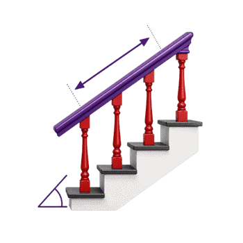
- Slanted spacing is measured along the incline of the stair railing.
- All compatible measurements are converted to a common unit before calculation.
- Intermediate calculations retain full precision until final results are displayed.
- Users verify calculated spacing against local codes, drawings, and site conditions.
Results are rounded for display.
Internal calculations use full precision.
Formulas Used in Spindle Spacing Calculator :
1. Length Unit Conversion
All length measurements are converted to one base unit before calculation.
2. Required Number of Spindles
The result is restricted to a positive whole number because partial spindles cannot be installed.
3. Even Spindle Spacing
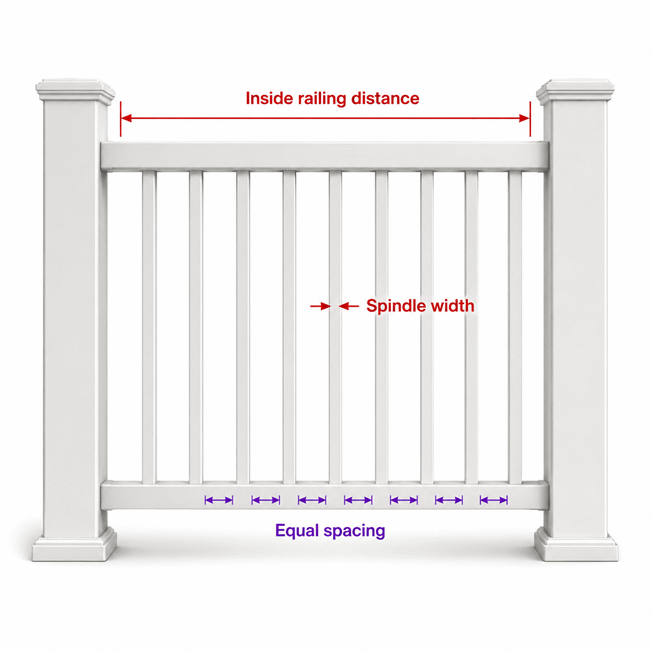
The remaining open distance is divided equally among the two end gaps and all internal gaps.
4. Centered Spindle-to-Spindle Spacing
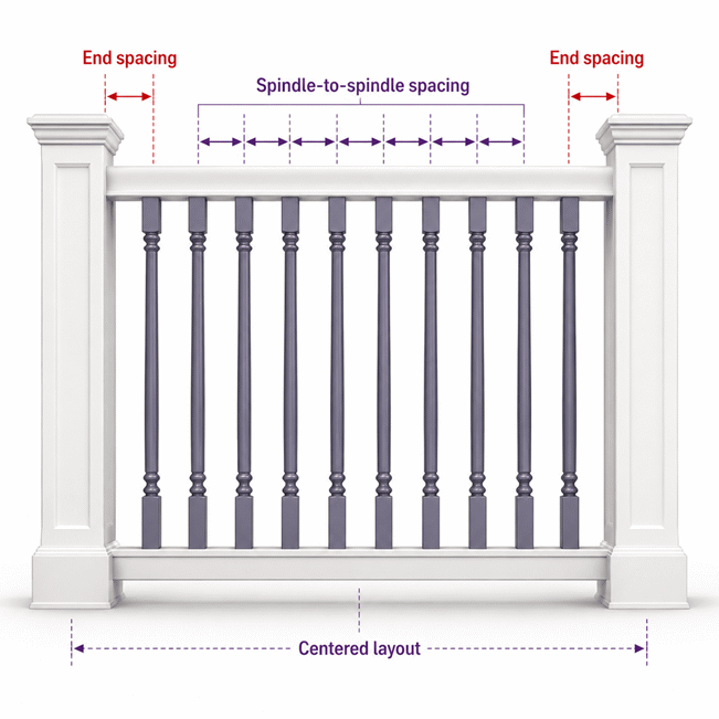
The selected maximum spacing is maintained between adjacent spindles in the centered layout.
5. Centered End Spacing
The unused distance is divided equally between the two ends of the railing section.
6. Stair Pitch
Riser rise and effective tread run must use compatible length units.
7. Degree-to-Radian Conversion
Trigonometric calculations use the stair pitch in radians.
8. Slanted Stair Spacing
The same conversion applies to even gaps, centered internal gaps, and centered end gaps.
9. Reverse Calculation for an Even Layout
This relationship restores the required railing distance from an edited even-spacing result.
10. Reverse Calculation for a Centered Layout
This relationship restores the railing distance after changing a centered spacing result.
11. Final Display Rounding
Intermediate values retain full precision; rounding is applied only to the displayed result.
Variable Definitions
- xb
- Measurement expressed in the base length unit
- xu
- Measurement entered in the selected unit
- ku
- Conversion factor from the selected unit to the base unit
- L
- Inside railing distance
- w
- Finished width of one spindle
- gmax
- Maximum allowable clear spacing
- N
- Required whole number of spindles
- ge
- Clear spacing for the evenly-spaced layout
- gc
- Internal clear spacing for the centered layout
- e
- Clear spacing at each railing end
- R
- Vertical riser rise
- T
- Horizontal effective tread run
- θ
- Stair pitch used in trigonometric calculations
- gh
- Horizontal projection of a stair spacing
- gs
- Corresponding spacing measured along the stair slope
- xcalculated
- Full-precision result before display rounding
- xdisplay
- Final value shown to the user
Variables & Definitions
View a complete list of all variables used in this calculator, including definitions and units
Spindle Spacing Calculator Variables and Measurement Definitions
| Symbol | Variable | Definition | Value Type or Unit | Used For |
|---|---|---|---|---|
| xb | Base measurement | A measurement converted to the calculator's common base length unit. | Base length unit | Unit normalization |
| xu | Entered measurement | The numerical measurement entered in the unit selected by the user. | Selected length unit | Unit conversion input |
| ku | Unit conversion factor | The multiplier that converts the selected length unit to the base unit. | Dimensionless factor | Unit normalization |
| L | Inside railing distance | The clear distance between the inside faces of the two railing posts. | Length | Spindle count and layout |
| w | Spindle width | The finished width of one spindle measured across the railing section. | Length | Total occupied spindle width |
| gmax | Maximum allowable spacing | The greatest permitted clear opening between adjacent spindles. | Length | Spindle count and centered spacing |
| N | Number of spindles | The positive whole number of spindles required for the railing section. | Positive integer | Material quantity and spacing |
| ge | Even spindle spacing | The equal clear gap applied between every spindle and at both railing ends. | Length | Evenly-spaced layout |
| gc | Centered internal spacing | The clear gap maintained between adjacent spindles in a centered layout. | Length | Centered layout |
| e | End spacing | The equal clear distance from each end post to the nearest spindle. | Length | Centered layout |
| R | Riser rise | The vertical rise used to determine the inclination of a stair flight. | Length | Stair pitch calculation |
| T | Effective tread run | The effective horizontal run corresponding to one stair rise. | Length | Stair pitch calculation |
| θ | Stair pitch | The angle between the inclined stair railing and the horizontal direction. | Degrees or radians | Slanted spacing conversion |
| θdeg | Stair pitch in degrees | The stair pitch expressed in degrees for user input and display. | Degrees | Angle input and display |
| θrad | Stair pitch in radians | The stair pitch converted to radians for trigonometric calculations. | Radians | Cosine calculation |
| gh | Horizontal spacing | The horizontal projection of an even, internal, or end stair spacing. | Length | Slanted spacing conversion |
| gs | Slanted spacing | The corresponding spacing measured along the inclined stair railing. | Length | Stair spindle layout |
| xcalculated | Calculated result | The full-precision numerical result retained before display rounding. | Calculated value | Precision control |
| xdisplay | Displayed result | The final calculated value rounded for clear on-screen presentation. | Rounded value | Result display |
Unit Conversion Table
Railing and Spindle Length Unit Conversion Table
| Unit Group | Unit Name | Symbol | Equivalent in Meters | Used For |
|---|---|---|---|---|
| Metric Length | Millimeter | mm | 0.001 m | Spindle width, clear gaps, end spacing, rise, and tread run |
| Metric Length | Centimeter | cm | 0.01 m | Spindle width, allowable spacing, rise, and tread run |
| Metric Length | Meter | m | 1 m | Inside railing distance and longer deck or stair sections |
| Imperial Length | Inch | in | 0.0254 m | Spindle width, clear gaps, end spacing, rise, and tread run |
| Imperial Length | Foot | ft | 0.3048 m | Inside railing distance and complete railing sections |
| Imperial Length | Yard | yd | 0.9144 m | Long railing runs and preliminary project measurements |
Stair Pitch Unit Conversion Table
| Unit Group | Unit Name | Symbol | Equivalent in Radians | Used For |
|---|---|---|---|---|
| Angle | Degree | deg | π / 180 rad | Stair pitch input and display |
| Angle | Radian | rad | 1 rad | Stair pitch trigonometric calculation |
Example Calculation
Seventeen spindles fit within the 240 cm railing section while keeping the evenly distributed horizontal gaps below the selected 10 cm limit.
The evenly-spaced layout produces identical 9.56 cm gaps at both ends and between every spindle.
The centered layout keeps 10 cm internal gaps and divides the remaining distance into two 6 cm end gaps.
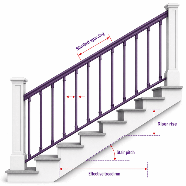
Stair measurements are longer along the incline, so horizontal gaps are divided by the cosine of the 32.74° pitch.
The slanted spacing is first projected horizontally using the cosine of the stair pitch.
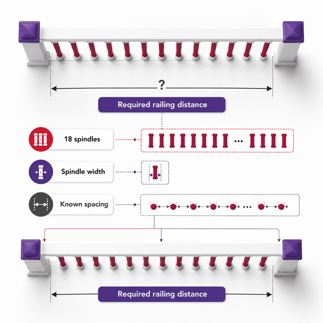
Eighteen spindles occupy 63 cm, while nineteen equal gaps occupy 167.20 cm.
Adding the spindle width and total gap width gives a required railing distance of 230.20 cm.
The recovered distance can be used to verify a design or determine the required opening.
Results are rounded for display.
Internal calculations use full precision.
Calculations Disclaimer
Measure the Railing Opening Before a Small Error Controls the Entire Layout
A railing project often fails before the first spindle is installed. The problem usually begins with one careless measurement. A builder records the outside railing length instead of the clear opening. Every later mark then moves away from its correct position.
Start by identifying the exact section that will contain the spindles. Measure between the finished inside faces of both posts. If one end meets a wall, measure to its finished surface. Skirting, trim, post sleeves, and brackets may reduce the usable opening.
Take the measurement where the spindle layout will actually be marked. The top and bottom rails may not have identical lengths. Posts may also lean slightly or sit out of square. Check the opening near both rails before choosing a final layout.
Measure the Installed Spindle Instead of Trusting Its Product Name
A listed spindle size may describe a nominal product category. It may not match the finished width. Paint, powder coating, sleeves, collars, and decorative profiles can change the installed dimension. Measure a real sample with a reliable tool.
Decorative spindles need extra attention. Their width can change from top to bottom. Select one consistent guide line for every measurement. This line should match the planned marking and inspection position.
Measure several pieces from the same order. Manufacturing tolerances can create small width differences. One unusual piece should not define the whole layout. Record the typical finished width and inspect visible variations before installation.
Use a Measurement Checklist Before Opening the Calculator
- Confirm the finished inside distance between both supports.
- Measure the actual spindle at the chosen guide line.
- Check both ends for trim, sleeves, brackets, or obstructions.
- Inspect the top and bottom rail lengths separately.
- Record every railing section as an independent opening.
- Repeat doubtful measurements before marking permanent positions.
A thirty-second measurement check can prevent hours of drilling, filling, and realignment.
The AxiCalculator Spindle Spacing Calculator turns these measurements into a clear layout. It cannot repair an incorrect field measurement. Accurate input remains the fastest path to a balanced railing.
Choose Even or Centered Spacing Before the End Gaps Become a Surprise
A common installation problem appears at the final spindle. The internal gaps look consistent, but the last opening looks noticeably different. This happens when the layout method was never selected before marking began.
An evenly spaced layout distributes the available opening across every clear gap. Both end spaces match the gaps between adjacent spindles. This creates a calm visual rhythm across the entire railing section.
An even layout works well for visible deck rails and modern interiors. It also reduces awkward correction near the final post. Every spindle belongs to one continuous pattern from start to finish.
Centered Spacing Preserves the Internal Gap and Balances Both Ends
A centered layout follows a different visual rule. The selected internal distance remains consistent between neighboring spindles. The unused space is then shared equally between both railing ends.
This option can suit renovations where existing spindle spacing must continue. It also helps when nearby railing sections share an established pattern. However, the end spaces may differ from the internal spaces.
Compare both layouts before drilling. One layout may look balanced on a short section. The other may work better across a longer opening. The calculator allows this comparison without repeated manual marking.
EVEN LAYOUT → Equal end gaps → Equal internal gaps → Continuous visual rhythm
CENTERED LAYOUT → Fixed internal gaps → Balanced end spaces → Preserved pattern
Do not select a layout only because its numbers look familiar. Consider post width, spindle style, sightlines, and nearby sections. A decorative railing often needs visual balance as much as mathematical balance.
Long sections can magnify tiny differences. Short sections can make end gaps more noticeable. Review the complete elevation from a normal viewing position. A close inspection alone may hide an obvious visual imbalance.
The best layout is not the one with the easiest marks. It is the one that finishes cleanly.
Use AxiCalculator to compare the two spacing styles before buying or cutting materials. This quick decision can reduce waste and prevent visible compromises near the final post.
Plan Deck Spindles as Separate Sections Instead of Treating the Railing as One Line
A deck railing may look like one continuous structure. In practice, each post pair creates a separate layout problem. Applying one spacing result everywhere often produces mismatched end gaps and inconsistent spindle counts.
Measure each clear section independently. Label the sections before recording their dimensions. Simple names like Front A, Front B, and Stair Return reduce confusion. Keep each measurement beside its matching section label.
Account for Finished Posts, Sleeves, Corners, and Hardware
Post sleeves can reduce the available opening after the frame is built. Mounting plates and decorative collars may create further conflicts. Corner posts can also change the visible start point of a spindle pattern.
Complete the measurement after these components are selected. If that is impossible, use their verified finished dimensions. Do not estimate decorative thickness from a catalogue image.
Check whether spindle connectors add visible width. Some systems hold the spindle within a narrow socket. Others use a larger bracket around its edge. The chosen hardware can affect both appearance and marking positions.
Create a Section Schedule Before Ordering Materials
A section schedule prevents missing pieces and duplicate measurements. It also creates a useful record for installation. Include the section name, clear opening, spindle style, quantity, and layout choice.
Keep spare materials separate from the calculated installed quantity. Spares cover damage, colour mismatch, and later repairs. The correct allowance depends on product availability and project conditions.
MEASURE → Label each section → Check finished hardware → Compare layouts
PLAN → Confirm quantities → Review sightlines → Prepare marking positions
INSTALL → Dry-fit first → Check both ends → Drill only after approval
Deck exposure creates another concern. Wood movement, coating thickness, and seasonal conditions can affect installation. Follow the railing manufacturer’s fastening and clearance instructions. Never enlarge an opening simply to absorb construction movement.
Material selection should remain separate from spacing design. Wood offers easy field adjustment but may move with moisture. Metal provides a slim profile but needs accurate drilling. Composite systems often depend on dedicated connectors and fixed product dimensions.
Before purchasing, confirm compatibility between spindles, rails, connectors, and post systems. Review finish coverage, replacement availability, packaging quantities, and documented warranty terms. Warranty conditions should come directly from the selected manufacturer or seller.
AxiCalculator supports planning, but the product system controls installation details. Use both forms of information together. This separation keeps the layout accurate and the purchase decision practical.
Handle Stair Spacing Carefully Because the Visible Distance Changes With the Viewing Line
Stair projects often create confusion after materials arrive. A spacing that looked correct horizontally appears larger along the sloped rail. The installer then changes marks without checking the original measurement line.
First identify how the spindles will connect. Some spindles sit on a sloped base rail. Others attach directly to individual treads. These arrangements do not share the same marking process.
The calculator’s stair layout assumes a consistent inclined railing system. The spindles remain vertical while the supporting rail follows the stair pitch. Rise and effective tread run describe that incline.
Keep One Guide Line From the First Measurement to the Final Mark
Select a repeatable guide line across every spindle. This matters when decorative profiles change width. The horizontal opening and sloped rail distance describe different paths. Mixing those paths creates false spacing.
Check the stair pitch across the complete flight. Existing stairs may contain small variations. One tread may be deeper than another. One riser may also differ because of finished flooring.
Measure finished surfaces whenever possible. Carpet, timber overlays, tile, and nosing details can change effective dimensions. A rough structural measurement may not describe the completed stair.
Inspect the Stair From Both Safety and Visual Positions
Look along the handrail from the bottom landing. Misaligned spindles become obvious from this position. Then inspect the flight from the side. Confirm that the top and bottom connections follow a consistent line.
Dry-fit several spindles before drilling the full flight. This reveals connector conflicts and profile changes. It also shows whether the proposed rhythm suits the stair geometry.
A stair layout can pass a tape-measure check yet still look wrong from below.
Do not assume every stair requires the same number of spindles per tread. Tread depth, spindle width, post position, and attachment style all matter. Treat simple rules of thumb as planning clues, not final instructions.
Stair alterations deserve extra care around children and high-traffic areas. Loose fittings and oversized openings create avoidable risks. Confirm the completed design with the applicable authority and product instructions before installation.
The AxiCalculator stair mode helps compare horizontal and sloped measurements. It also shows how the chosen pitch changes the distance along the rail. This makes unusual results easier to understand before work begins.
Prevent Marking Drift Before Repeated Small Errors Reach the Final Post
A builder may calculate the correct gap and still finish incorrectly. The usual cause is repeated measurement from the previous spindle. Each small marking error then carries into the next position.
Use one fixed reference point for the entire section. Mark cumulative positions from the same post face. This prevents earlier errors from moving every later spindle.
Mark Centerlines When Spindle Edges Are Difficult to Follow
Centerlines are often easier to repeat than decorative edges. They also work well with drilling templates and spindle sockets. Confirm how each centerline relates to the visible clear opening.
Use a sharp pencil or fine marking knife. Thick marks create uncertainty during drilling. On dark metal, use removable high-contrast tape. Mark the tape instead of damaging the finished surface.
Clamping a straight guide can improve alignment. A story pole can also transfer repeated positions. Verify the story pole against the complete section before using it elsewhere.
Dry-Fit the First, Middle, and Final Spindles
Place temporary spindles at both ends and near the centre. Step back and inspect the pattern. Check that connectors sit squarely and clear nearby hardware.
Next, place the remaining spindles without permanent fasteners. Confirm every opening visually and physically. A dry fit exposes errors while corrections remain inexpensive.
Do not drill every hole after checking only the first mark. One incorrect reference can damage both rails. Review the first, middle, and final positions before committing.
Installation tools also affect accuracy. A worn tape hook can change short measurements. An oversized drill bit can allow visible movement. A poor square can tilt spindle positions across the railing.
Clean tools and stable work supports improve repeatability. Secure each rail before drilling. Avoid marking on an unsupported rail that bends under hand pressure.
For long projects, divide inspection into checkpoints. Review each completed section before moving forward. This catches systematic errors before they spread across the deck or stair.
Use the calculator’s exported measurements as a project record. Keep the file with section labels and material details. This information can support future repairs or matching extensions.
Separate Technical Layout Decisions From the Spindle Purchase Decision
A buyer can choose attractive spindles that do not fit the planned system. The style looks right, but connectors, rail dimensions, or replacement supply cause delays. Technical fit must be confirmed before price comparison.
Start with the installed environment. Indoor stairs, exposed decks, coastal locations, and public spaces create different demands. Material, finish, fastening method, and maintenance needs should match that environment.
Compare Products Using Finished Dimensions and Installation Requirements
Record the actual spindle width, available lengths, connector type, and compatible rail system. Check whether the spindle can be trimmed. Confirm whether trimming affects its finish or warranty.
Review package quantities before ordering. A low unit price can hide an inconvenient pack size. Delivery cost, replacement access, and required connectors also affect the total purchase.
Ask for clear product documentation. Useful documents include installation instructions, finish guidance, and warranty conditions. Product photos alone cannot confirm system compatibility.
Original packaging can help with identification, but packaging does not prove suitability. Compare product codes and physical dimensions with official documentation. Buy through a seller that provides traceable order records.
Evaluate Support Before the Installation Problem Appears
Reliable support should answer technical questions before purchase. Ask how damaged items are handled. Confirm replacement availability and the process for warranty claims.
Do not assume every finish carries the same coverage. Coastal exposure, incorrect cleaning, cutting, and field coating may affect protection. Read the applicable written terms before ordering.
AxiCalculator helps define the quantity and spacing plan. That information makes supplier discussions more precise. You can share clear dimensions instead of describing the project from memory.
Use the calculator before requesting a quotation. Compare the even and centered layouts. Confirm the expected quantity for every section. Then request pricing for the selected system and necessary hardware.
This order protects the project from expensive changes. First establish the layout. Then verify product compatibility. Finally, compare price, support, delivery, and documented coverage.
The result is a calmer purchase decision and a cleaner installation plan. You know what must fit before choosing what to buy. You also gain a repeatable record for installers, suppliers, and future maintenance.
Start your layout with the AxiCalculator Spindle Spacing Calculator. Review every section before ordering materials. A few careful minutes can protect the appearance of the entire railing.
Frequently Asked Questions
What should I do when the railing opening is wider at one rail than the other?
Can I replace one damaged spindle without recalculating the entire railing section?
How should I plan spindle spacing around gates, removable panels, or access openings?
Can the same spindle layout be copied to another railing with a similar length?
How can an engineer include installation tolerance without exceeding the design gap?
How should spindle spacing be checked when decorative profiles change along the stair pitch?
How can calculated centerlines be transferred accurately across a long fabricated railing?
Engineering Resources
Our engineers are here to help you get it right.