SAG Calculator
- Last formula update:
Decimal & Rounding Policy
- The SAG Calculator keeps full numerical precision throughout every intermediate calculation.
- Displayed results use up to 12 significant digits and remove unnecessary trailing zeros.
- Decimal inputs are accepted for radius, diameter, and SAG in all supported units.
- Values are never rounded before applying the SAG, radius, or diameter formulas.
- Very small or very large results may use scientific notation for readability.
- Final displayed precision may vary slightly after unit conversion to preserve accuracy.
Valid range
- Radius of curvature (R): Must be greater than zero and support the selected chord and SAG.
- Diameter (d): Must be greater than zero and must satisfy d ≤ 2R.
- SAG (s): Must be greater than zero and must satisfy s ≤ R.
- When Diameter and SAG are known, the minor-segment condition requires 2s ≤ d.
- Supported converted values range from 1e-12 m to 1e12 m.
- Any two valid parameters can be entered to calculate the remaining parameter automatically.

Reviewers:
Elvarine Jexmont
Fenrick Zorquell
Check our editorial policy
August 13, 2026
1.0.0
Initial calculator and formula release.
Our engineers are here to help you get it right.
What Does the SAG Calculator Tell You Before You Trust the Result?
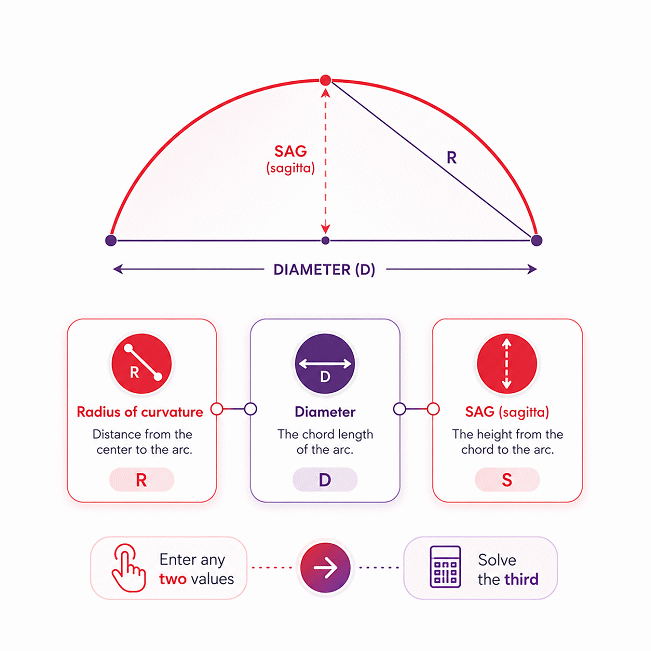
SAG Calculator helps you find SAG, radius of curvature, or chord length from any two valid measurements. It is built for minor circular segments, so the measured span must represent the chord between two points on the same circular arc. The SAG Calculator also supports reverse solving, which is useful when the circle center is hidden or direct radius measurement is impractical.
Use clean, repeatable field measurements before trusting the result. Mark both chord endpoints, locate the true midpoint, and measure SAG perpendicular to the chord. A stable straight edge and consistent contact points improve reliability.
- Enter any two valid geometric values to solve the third automatically.
- Treat the displayed diameter as the chord span unless it passes through the circle center.
- Use this method only for circular geometry, not cables, parabolas, ellipses, or irregular curves.
- Repeat important measurements to catch midpoint, probe-angle, or contact-point errors.
- Small SAG errors can cause large radius changes on shallow arcs.
- Real parts may differ because of heat, load, wear, deformation, or manufacturing tolerances.
- Use results for fast engineering checks, fabrication planning, inspection, fit-up, and field verification.
- For high-risk work, confirm the geometry with drawings, repeat measurements, and qualified technical review.
Assumptions used in this calculator
What Does the SAG Calculator Tell You Before You Trust the Result?
SAG Calculator helps you find SAG, radius of curvature, or chord length from any two valid measurements. It is built for minor circular segments, so the measured span must represent the chord between two points on the same circular arc. The SAG Calculator also supports reverse solving, which is useful when the circle center is hidden or direct radius measurement is impractical.
Use clean, repeatable field measurements before trusting the result. Mark both chord endpoints, locate the true midpoint, and measure SAG perpendicular to the chord. A stable straight edge and consistent contact points improve reliability.
- Enter any two valid geometric values to solve the third automatically.
- Treat the displayed diameter as the chord span unless it passes through the circle center.
- Use this method only for circular geometry, not cables, parabolas, ellipses, or irregular curves.
- Repeat important measurements to catch midpoint, probe-angle, or contact-point errors.
- Small SAG errors can cause large radius changes on shallow arcs.
- Real parts may differ because of heat, load, wear, deformation, or manufacturing tolerances.
- Use results for fast engineering checks, fabrication planning, inspection, fit-up, and field verification.
- For high-risk work, confirm the geometry with drawings, repeat measurements, and qualified technical review.
Results are rounded for display.
Internal calculations use full precision.
Formulas Used in SAG Calculator :
- R = radius of curvature
- d = diameter spanning the arc endpoints
- s = SAG or sagitta
- xu = value entered in the selected unit
- ku = conversion factor from the selected unit to meters
- xm = normalized value in meters
1. Normalize the selected unit
All geometric calculations use normalized length values before the result is converted back to the selected display unit.
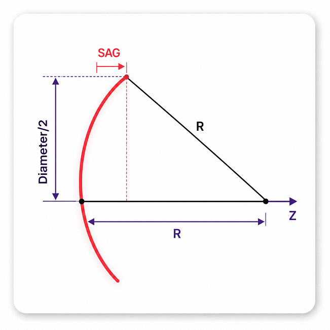
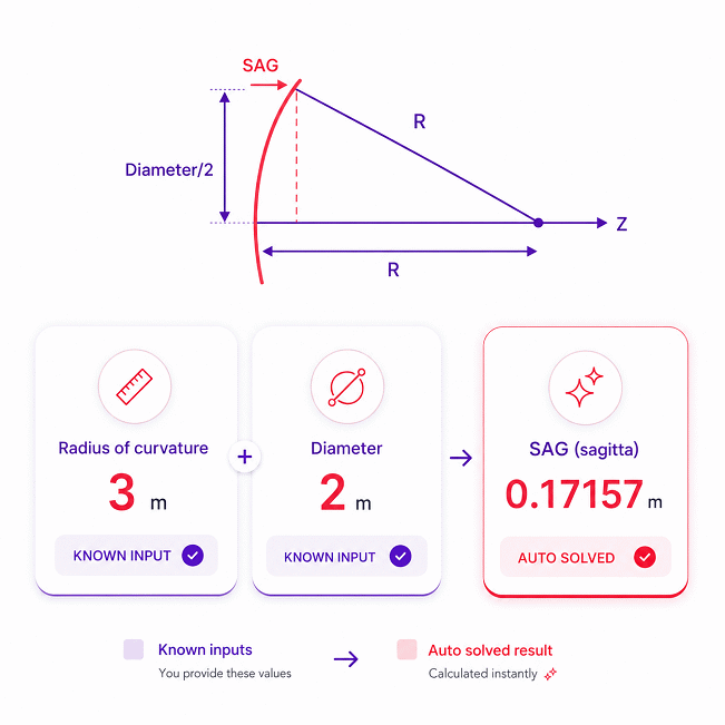
2. Calculate SAG from radius and diameter
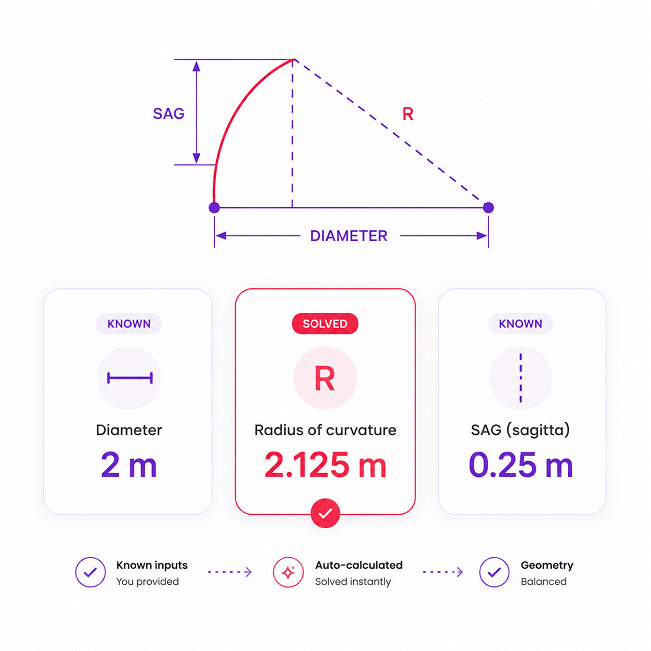
3. Calculate radius of curvature from diameter and SAG
4. Calculate diameter from radius and SAG
Variables & Definitions
View a complete list of all variables used in this calculator, including definitions and units
SAG Calculator Variables and Units
| Variable | Parameter | Definition | Unit | Calculation Role |
|---|---|---|---|---|
| R | Radius of curvature | Radius of the circle that defines the curved segment. | Length unit | Can be entered directly or calculated from diameter and SAG. |
| d | Diameter | Distance spanning the two endpoints of the curved segment. | Length unit | Can be entered directly or calculated from radius and SAG. |
| s | SAG (sagitta) | Perpendicular depth from the midpoint of the span to the arc. | Length unit | Can be entered directly or calculated from radius and diameter. |
| xu | Selected-unit value | Numerical value entered or displayed in the selected length unit. | Selected length unit | Provides the value used before conversion to the internal base unit. |
| ku | Unit conversion factor | Factor used to convert the selected length unit into meters. | m per selected unit | Normalizes entered values before geometric calculations are performed. |
| xm | Normalized value | Physical length after conversion to the calculator's internal base unit. | m | Provides a consistent base value for all internal calculations. |
Unit Conversion Table
SAG Calculator Unit Conversion Table
| Unit Group | Unit Name | Symbol | Equivalent in Meters | Used For |
|---|---|---|---|---|
| Popular Units | Meter | m | 1 m | General engineering and construction measurements |
| Popular Units | Centimeter | cm | 0.01 m | Small construction and fabrication dimensions |
| Popular Units | Millimeter | mm | 0.001 m | Precision fabrication and mechanical measurements |
| Popular Units | Inch | in | 0.0254 m | US fabrication and construction measurements |
| Popular Units | Foot | ft | 0.3048 m | US construction and structural dimensions |
| SI Units | Kilometer | km | 1000 m | Large-scale civil and infrastructure geometry |
| SI Units | Decimeter | dm | 0.1 m | Intermediate metric length measurements |
| SI Units | Micrometer | um | 0.000001 m | Precision manufacturing and surface measurements |
| Imperial / US Units | Yard | yd | 0.9144 m | Construction layouts and larger US measurements |
| Imperial / US Units | Mile | mi | 1609.344 m | Large-scale infrastructure and surveying distances |
| Scientific Units | Nanometer | nm | 0.000000001 m | Microscopic geometry and high-precision scientific measurements |
| Oil & Industrial Units | Mil | mil | 0.0000254 m | Industrial tolerances, coatings, and fabrication measurements |
| Oil & Industrial Units | Microinch | uin | 0.0000000254 m | Surface finish and high-precision industrial measurements |
Example Calculation
A circular segment with a 7.5 m radius of curvature and an 8 m span has a SAG of approximately 1.1557 m. The calculation uses the minor circular segment relationship and retains full precision before display formatting. The diameter remains below twice the radius, so the geometry satisfies the required calculation domain. Any two valid geometric parameters can likewise be used to calculate the remaining value.
This reverse calculation starts with a known 6.4 m diameter and 0.8 m SAG. The calculator rearranges the circular-segment relationship to solve the unknown radius directly. The resulting radius of curvature is 6.8 m, and all three values satisfy the minor-segment geometry. The same reverse-solving logic allows any valid pair of parameters to determine the remaining value.
Results are rounded for display.
Internal calculations use full precision.
Calculations Disclaimer
What Does a SAG Calculator Really Tell You?
A curved part can look right and still be wrong. A SAG Calculator helps you check that curve fast. The SAG Calculator can also work backward from known values. This is useful when the circle center is hidden. It also helps when only part of the arc is easy to reach.
The tool links the span, the curve depth, and the radius. You can start with the two values you know. The tool then finds the third value. This makes the process useful in shops and on job sites. You do not need to rebuild the full circle first.
Why one curve can raise three different questions
Real work does not always give you the same data. One job may show the span and depth. Another job may give the radius and span. A third job may need the span from known curve data. A tool with reverse solving can handle all three cases.
This saves time when access is poor. A wall may hide the circle center. A frame may block a direct radius check. A large arc may place the center far away. In each case, the visible part can still give useful data.
What should you measure first?
Start with the values you can measure well. Do not choose a value just because it sounds familiar. A bad reading will weaken the final result. A clean span is often easy to repeat. A center depth can also be checked more than once.
If a design radius is known, use it with a clean span. If the radius is unknown, use two field readings. Mark the points before you measure. Keep both readings on the same part of the curve.
Quick check: use the best field data, not the easiest guess.
No calculator can fix a poor field reading. Good input gives a useful result. That rule matters more than any screen layout. It also makes later checks much easier.
Before you move on, check one more thing. Ask whether the chosen arc is truly the one you need. A large part may hold several local curves. The same part may also have wear or dents. Your chosen line should match the work decision you plan to make.
How Reverse Solving Helps When the Circle Center Is Hidden
A hidden circle center can stop a normal radius check. Reverse solving gives you another path. You can start with two values taken from the curve. The tool then finds the missing value. This is helpful during repair, fit-up, and site checks.
Reverse solving also helps before shop work starts. A fixed opening may already be set. The needed curve depth may also be known. Those values can help you check the target radius. This can reveal a bad plan before material is cut.
Measure what you can actually reach
Access is often the real problem. Walls, guards, frames, or trim can block key points. Large arcs can make direct radius checks hard. The full circle may not even exist as a real part.
Choose two points that are easy to reach. Make sure both points sit on the same arc. Use a firm edge for the span. Then take the depth at the true middle point.
This method keeps the work tied to real points. It also makes the check easy to repeat. Another person can use the same marks. That helps when teams must agree on one result.
Use a second check when the result matters
A result is stronger when you can test it again. Reset the tools and take new readings. Do not reuse the first setup without a check. A fresh setup can show small errors.
If both runs give close results, confidence goes up. If they do not, inspect the setup first. Check the end points and the middle point. Also check the straight edge and probe path.
A strange result can save money when it finds a bad setup early.
Reverse solving is not a way to skip good field work. It is a way to use field work better. The main gain is choice. You can use the values that are easiest to trust.
Reverse solving also helps when old drawings are missing. It can turn field data into a useful shape check. That does not prove the full design history. It does give the team a clear starting point. From there, they can compare other lines and records.
Why Chord and Diameter Are Easy to Confuse
A common word can hide a serious error. The word diameter often causes this issue. A span across an arc may only be a chord. That span does not always pass through the circle center.
A true diameter passes through the center of a circle. A chord joins two points on the circle. Every diameter is a chord. Yet many chords are not diameters. This matters when you check a shallow arc.
Focus on the end points, not the label
The physical points matter more than the name on a form. First mark the two arc points you want to use. Measure the straight span between them. Then find the middle of that same span.
The depth reading must match those two end points. Do not move one point after the span is set. Do not take depth on a nearby curve line. Small changes can create a new local shape.
Clear marks also help your team. One person can measure the span. Another can check the depth. Both can work from the same marked line. This reduces talk about terms and keeps focus on the part.
How to stop a label error before it spreads
Write the physical meaning beside the value. Use terms like chord span or full diameter when needed. On site notes, show the two end points. On a drawing, show the line used for the span.
The label may be wrong. The marked line should not be.
This small habit can prevent a chain of errors. It also makes old records easier to read. Good notes help the next person repeat the check. Clear shape data beats vague shop terms.
When you share the result, share the line used for the span. This small step avoids later doubt. It lets another person match your setup. It also helps when a new check is made days later.
Use the same terms in notes, drawings, and calculator records. This keeps the team aligned. It also reduces the chance that one person reads chord as full diameter. Clear wording is a small step with a large payoff today.
How to Measure SAG on Real Curved Work
A perfect math result can fail after one poor reading. SAG work needs a clean setup. The span must stay firm. The middle point must be clear. The depth path must be square to the span.
Build a clean and stable span
Pick two fixed points on the same arc. Place a straight edge between those points. Make sure the edge does not bend. Then mark the exact middle of the span.
Take the depth reading at that middle mark. Keep the probe square to the span. A tilted probe can read too long. The risk is greater when the true depth is small.
A simple square can help guide the probe. A fixed stand can help in shop work. The goal is not fancy gear. The goal is a setup that another person can repeat.
Surface condition can change the reading
Paint, weld beads, dirt, and rough stone can move contact points. Soft parts can also move under probe force. Clean the contact spots when you can. Use the same probe tip for each run.
Heat and load can change a real part too. A hot metal frame may shift as it cools. A loaded member may not match its free shape. Note the state of the part when this matters.
Do not trust one reading on important work. Remove the setup and build it again. Then compare the new reading with the first one. A close match is a useful sign.
Also check the area beside the chosen line. A dent can change one local arc. A weld can lift one end point. A worn edge can shift the true span. These are part problems, not calculator problems.
The safest field habit is simple. Mark, measure, reset, and measure again. This takes little extra time. It can stop a much larger shop error.
For long spans, support the straight edge if needed. A small bend can change depth. Check the edge before and after the reading. Keep hands away during the final check. Simple control of the setup can improve repeat work.
Common SAG Mistakes That Can Ruin a Good Result
The worst mistake often looks normal at first. The numbers may seem clean. The screen may show a neat result. Yet the shape behind those numbers may be wrong.
Using a round-arc tool on the wrong curve
Not every curve is part of a circle. Some parts use an oval shape. Some use a parabolic shape. Some are freeform by design. A loaded cable also follows other rules.
Check the design before you trust the result. Read the drawing or shop note. Ask how the part was formed. If the shape should be circular, this tool fits well. If not, choose the right model first.
Mixing points from different parts of the curve
A curve may change from one place to another. This is common on damaged parts. It can also happen on hand-formed work. The span and depth must come from one local line.
Mark that line before you take data. Keep all contact points on it. Take a photo when the check is important. This gives the next reviewer a clear record.
Ignoring repeat checks
One reading can hide a hand error. A second setup can expose it. If the readings move a lot, stop and inspect. Do not hide the spread by using an average.
Check for a bent straight edge. Check the true middle point. Check the probe angle. Check for dirt under the end points. Small setup faults can change a shallow-arc check.
Another mistake is using one local result for the whole part. A local arc only tells you about that area. It does not prove the full part has one radius. Check more than one line when full shape matters.
Do not let a neat screen create false trust. A useful answer starts with repeatable field work. The tool should support that work, not replace it.
Good teams also separate data errors from shape errors. First test the setup. Then test the part. This order avoids needless rework. It also stops a bad reading from being treated as a bad part.
If a result looks too good, test it again. Clean numbers can still come from bad points. A fast repeat check is often cheaper than later rework. Trust the process more than the first screen result.
Where SAG Checks Add Value in Real Work
A curved part may reach the job before its full shape is known. This can slow fit-up and repair work. A SAG check can recover useful shape data fast. It works best on parts meant to follow a circular arc.
Building, shop, and site work
Builders can check round arches and curved openings. Shop teams can check rolled plate and curved frames. Template makers can compare a real curve with a plan. Repair teams can measure old work before making new parts.
The same method helps with repeat checks. A shop can mark one fixed span on each part. The depth can then be checked at the same spot. This gives a simple way to compare parts.
Reverse solving can also help during fit-up. A field team may know the opening and curve depth. The tool can help link those values to the matching radius. That gives the team a clear shape check.
Machine and optical work
Large round parts can be hard to check by direct radius. The circle center may be far away. A local span and depth can offer a simpler path. This can help during machine setup and part checks.
Round optical surfaces use the same basic shape link. Care still matters when the work is very precise. Clean contact points and stable tools become even more important. The field method must match the level of the job.
When AxiCalculator fits the workflow
AxiCalculator is useful when you need a fast and clear curve check. You can start with the two values you already know. Reverse solving reduces extra field steps. The output is easy to review with your team.
Use the result as the first shape check. Then compare it with the drawing and field notes. Repeat odd readings before you act. For high-risk work, use an independent check as well.
The goal is not to replace sound judgment. The goal is to make shape checks faster. Better data can lead to better shop choices. It can also cut delay when a curve must be checked now.
These checks can also help during handover. A clear record can show what was checked. It can show where the check was made. That is useful when work moves between shop and site. It helps the next team start from known data.
When a Fast Check Is Enough and When Review Matters
A wrong choice can cost more than the check itself. Some jobs only need a quick shape result. Other jobs need a deeper review. The key is knowing which type of job you have.
Use the calculator for clear and routine curve checks
The tool works well for simple circular-arc tasks. It can help before cutting or forming work starts. It can support fit checks and field checks. It can also help when you test old work against a plan.
Keep the field notes with the result. Record where the span was taken. Note the state of the part. Save the drawing or photo with the check. Good records make later review much easier.
A shared result can also help a team move faster. Others can repeat the same check. They can compare their field data with yours. This is more useful than passing one number without context.
Use deeper review when the risk is higher
Some choices need more than one curve check. A safety link may need formal review. A costly part may need a set check plan. A tight fit may need a full tolerance review.
Noncircular parts may also need a different shape model. Do not force a round-arc tool onto them. Use the SAG Calculator as an early screen. Then move to the right review path.
For AxiCalculator users, the next step stays clear. Start with the quick curve check. Repeat the field data if the result looks odd. Save the result with useful notes. Ask for technical review when the job risk calls for it.
Fast math helps. A fast wrong choice does not.
This keeps routine work quick and higher-risk work careful. It also makes the tool easier to trust. Clear limits are part of good technical work. So is knowing when another check adds real value.
For team use, set one clear check method and keep it consistent. Use the same marks and tool path. This makes results easier to compare. It also helps new team members repeat the work correctly.
When in doubt, slow the decision before you speed the work. A short review can prevent waste. Clear notes can prevent repeat checks. A sound process makes the calculator more valuable across the whole team.
Frequently Asked Questions
When should I use a SAG Calculator instead of another curve calculator?
Can I find the radius if the center of the circle is impossible to reach?
Why can two people measure the same curved part and get different results?
Can I mix millimeters, inches, feet, or other length units in one calculation?
How should I verify the radius of a large fabricated arc when no center point exists?
Why does reverse-solving radius become unstable when the measured SAG is very small?
What should I check when the calculated radius does not match the CAD model?
Engineering Resources
Our engineers are here to help you get it right.